Skip to content
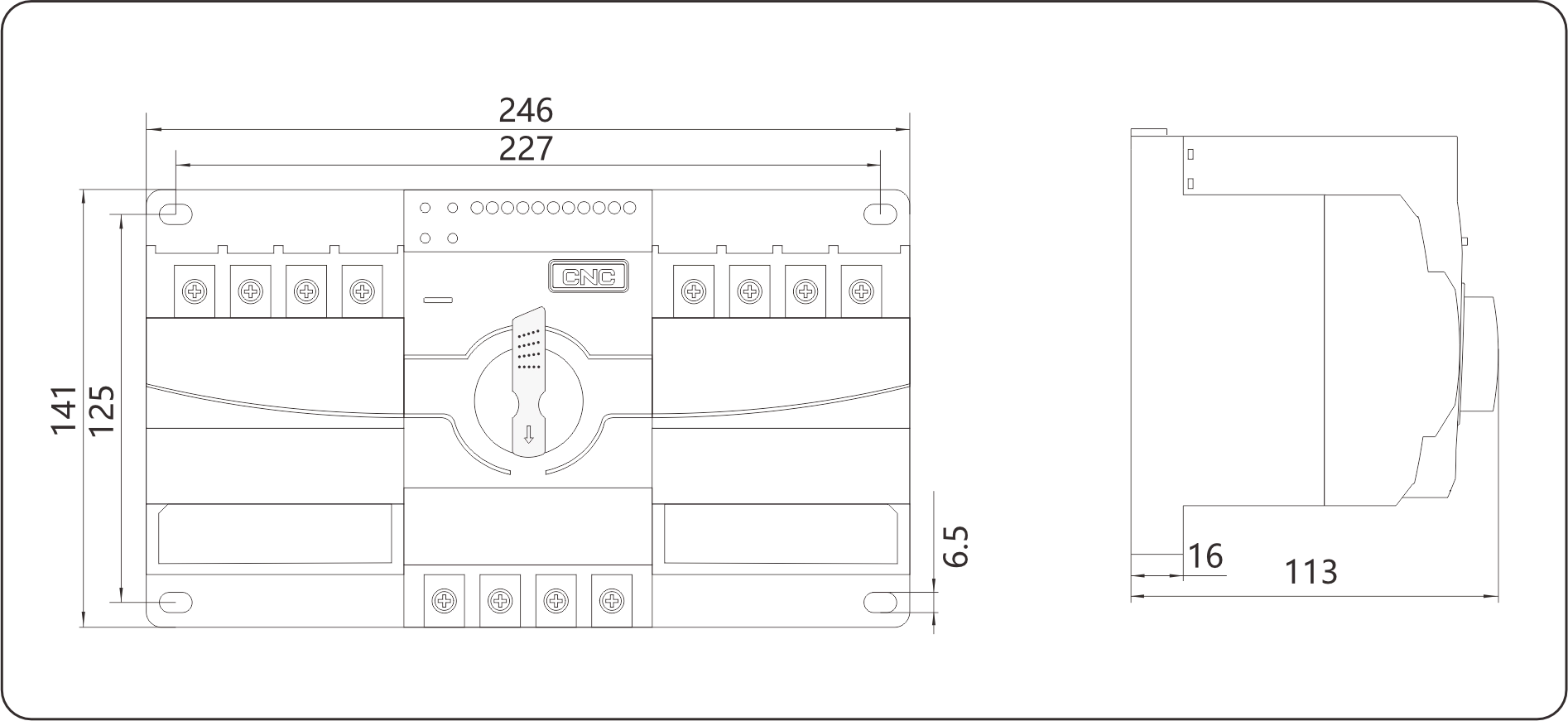
 | CZ9B | – | 63 | 4 | 125A |
| Model | Shell frame | Number of poles | Rated current | |
| ATS (CB class) | 63(16~63A) | 2:2P 3:3P 4:4P | 16A, 20A, 25A, 32A 40A, 50A, 63A |
| Model | CZ9B-63 |
| Rated current(A) | 6,10,16,20,25,32,40,50,63 |
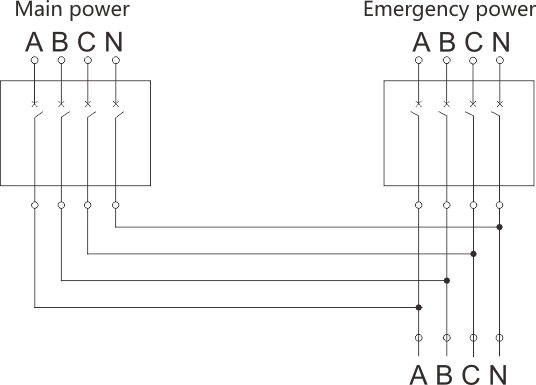
| Pole | 2P,3P,4P |
| Rated working voltage(V) | Single phase 230 |
| Three phase 400 | |
| Rated insulation voltage Ui | 500V |
| Rated impulse withstand voltage Uimp | 4kV |
| Rated short-circuit making capacity Icm | 7.5kA,Power-on time 0.1s |
| Rated making and breaking capacity Icn | 5kA,1.05Ue,cosφ=0.65 |
| Mechanical life | 10000 times |
| Electrical life | 6000 times |
| Transfer action time | ≤5s |
| Undervoltage/Overvoltage action value | 165/270±5V |
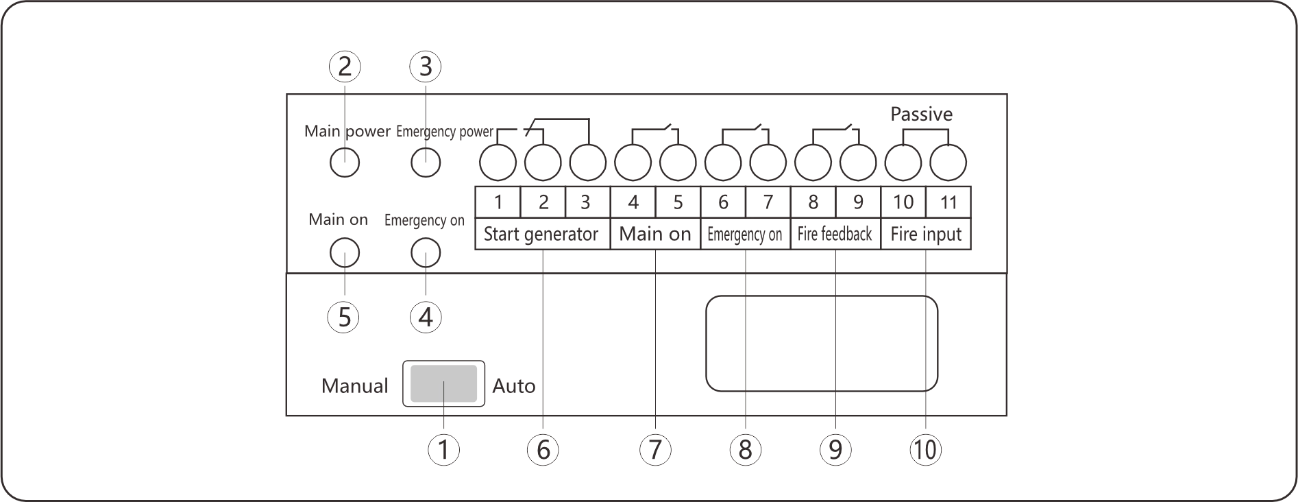
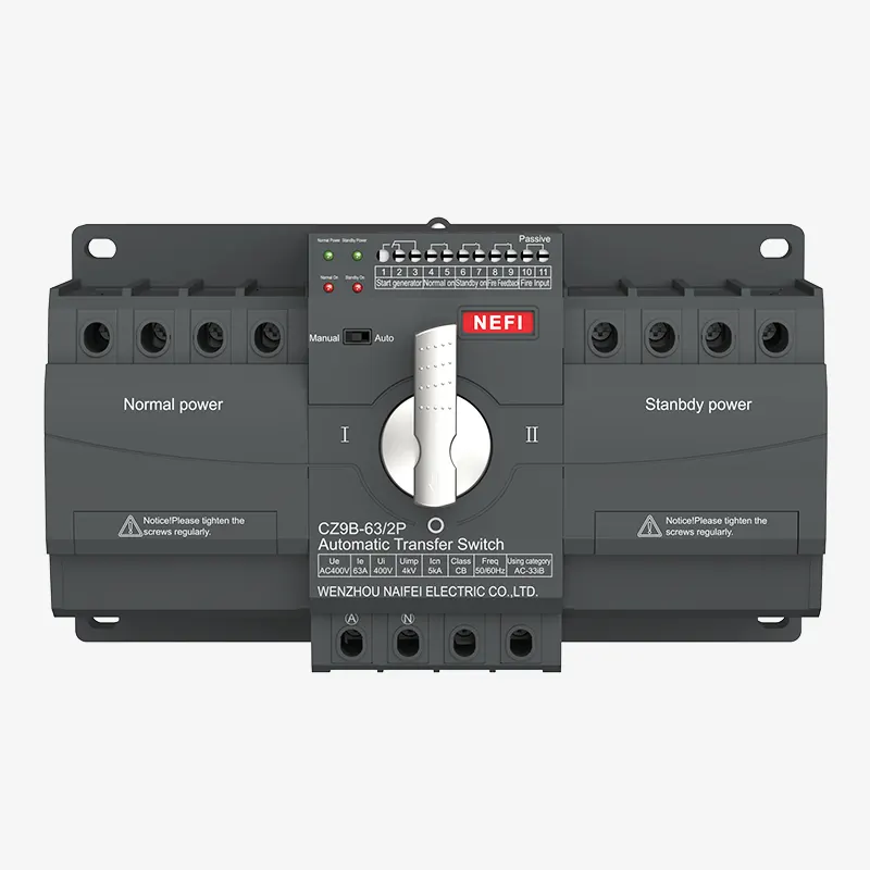
1 Auto/Manual Switch – Right = Auto mode; Left = Manual. Manual mode requires handle operation.
2 Main Power Indicator – When main voltage is normal, the indicator is ON. It turns OFF when phase is missing, flashes at 10Hz for overvoltage, and at 2Hz for undervoltage.
3 Emergency Power Indicator – When emergency voltage is normal, the indicator is ON. It turns OFF when a phase is missing, flashes at 10Hz for overvoltage, and at 2Hz for undervoltage.
4 Emergency ON Indicator –When the emergency circuit breaker is closed, this indicator on. Flashes slowly at 2Hz when the emergency circuit breaker trips.
5 Main ON Indicator – When the main circuit breaker is closed, this indicator on. Flashes slowly at 2Hz when the main circuit breaker trips.
6 Terminal 1, 2, and 3 are start-generator output terminals – When the main power is normal, ports 3 and 2 are OFF, while ports 3 and 1 are ON. When the main power is abnormal, ports 3 and 2 are ON, and ports 3 and 1 are OFF. It is recommended to connect normally closed contacts to ports 3 and 2.
7 Terminals 4–5 – Main power on state passive output port.
8 Terminals 6–7 – Emergency power on state passive output port.
9 Terminals 8–9 – Fire feedback: It is a passive output port. When the fire signal is connected and the product is powered off successfully, this port is closed.
10 Terminals 10–11 – Fire input: Passive input. When this port is short-circuited, the switch moves to the OFF position, and the main/emergency power indicators flash alternately. To exit fire mode, toggle the “Manual/Automatic” switch once, then return it to “Automatic”.
Notice:If the Main On or Emergency On indicator is flashing, manually check that the load side is normal. Then toggle the Manual/Auto switch to clear the fault. In manual mode, rotate the handle to open and close the circuit once.