Skip to content
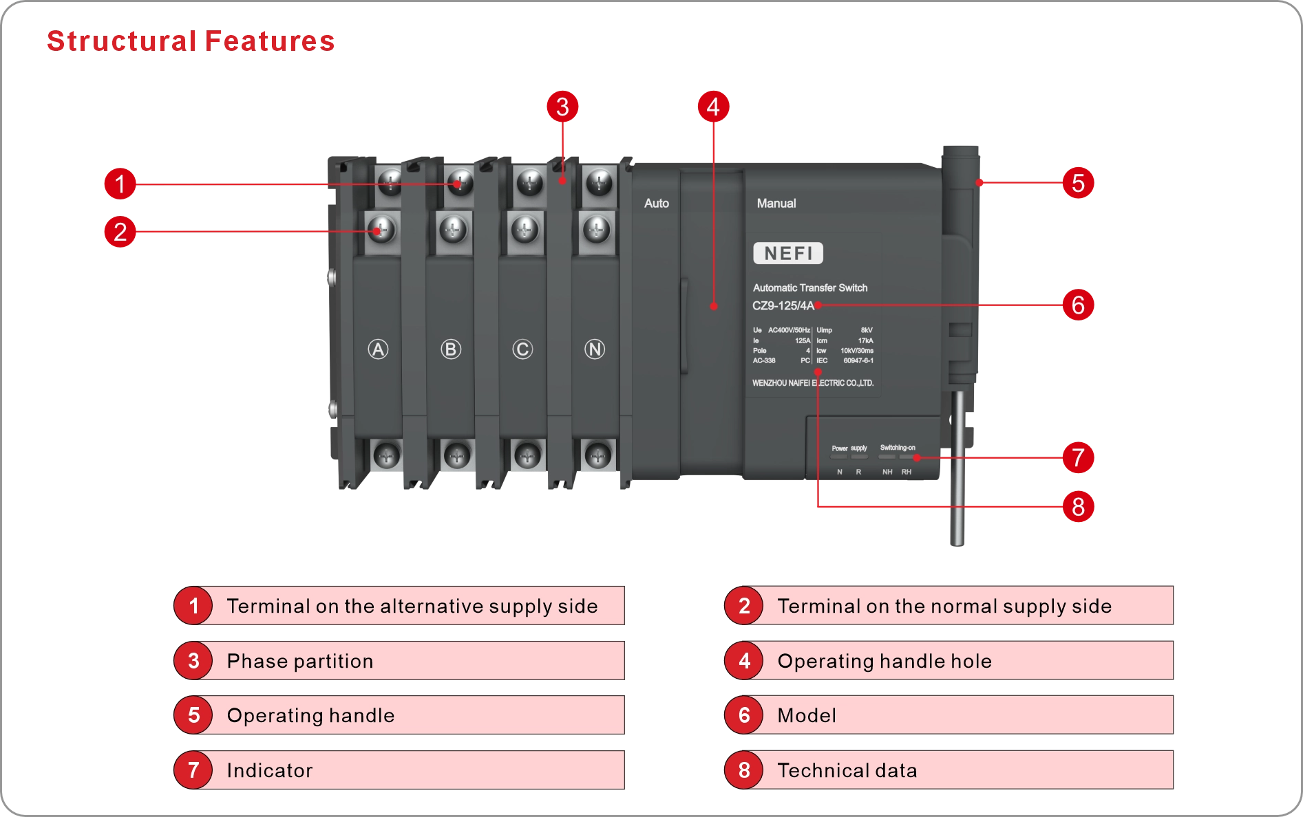
| CZ9 | – | 125 | 4 | A | 125A | FFD |
| Model | Shell frame | Number of poles | Controller type | Rated current | Function | |
| ATS (PC class) | 63(16~63A) 125(50~125A) 250(125~250A) 630(250~630A) | 2:2P 3:3P 4:4P | A: Economy | 16A, 20A, 25A, 32A 40A, 50A, 63A ,80A 100A, 125A, 160A, 200A 225A, 250A, 315A, 350A 400A, 450A, 500A, 630A | / | |
| B: Standard | /:Fire control linkage FF:Fire feedback D:Generator FFD:Fire feedback, Generator |
| Model | CZ9-63 | CZ9-125 | CZ9-250 | CZ9-630 |
| Function | Isolation,switch | |||
| Structure | Integrated | |||
| Electric equipment level | PC class | |||
| Utilization category | AC-33B | |||
| Number of poles | 2P, 3P, 4P | |||
| Electrical performance | ||||
| Rated insulation voltage Ui(V) | AC800 | AC1000 | ||
| Rated operating voltage Ue (V) | AC400(2P product AC230) | AC415 | ||
| Rated current le(A) | 16,20,25,32, 40,50,63 | 50,63,80, 100,125 | 125,160,200, 225,250 | 315,350,400 450,500,630 |
| Rated operating frequency(Hz) | 50 | |||
| Rated impulse withstand voltage Uimp(kV) | 8 | 12 | ||
| Rated impulse withstand current Icw(kA) | 5/30ms | 10/30ms | 25/1ms | |
| Rated short-circuit making capacity Icm(kA) | 8 | 17 | 52.5 | |
| Contact transfer time(s) | 0.6±20% | |||
| Operating transfer time(s) | 1.3±10% | |||
| Return time(s) | 1.3±10% | |||
| Power outage time(s) | 0.6±20% | |||
| Operation method | Auto/Manual | |||
| Switch position | Normal(I), Power outage(O),Standby (II) | |||
| Mechanical endurance(times) | 8000(*) | 4000(*) | ||
| Electrical endurance (times) | 2000(*) | 1000(*) | ||
| Applicable environmental conditions and installation | ||||
| Working temperature(℃) | -5~+40 | |||
| Altitude(m) | ≤2000 | |||
| Atmospheric conditions | The relative humidity of the atmosphere shall not exceed 50%at the highest ambient temperature of+40℃.At lower temperatures,there can be higher relative humidity,such as reaching 90%at+20℃ Special measures should be taken for occasional condensation caused by temperature changes; | |||
| Pollution degree | 3 | |||
| Installation environment | Places without obvious vibration and impact | |||
| EMC environment | Environment B | |||
| Protection degree | IP20 | |||
| Power supply voltage deviation range(V) | 160±10% | |||
| Normal working voltage range | 85%Ue~110%Ue | |||
| Installation | Vertical fixed installation | |||
| Wiring method | Screw wiring | |||
| Connection | Front connection | |||
| Maximum number of conductors allowed to be clamped in | 1 | 2 | ||
| Maximum screw torque | 2.5 | 6 | 10 | 22 |
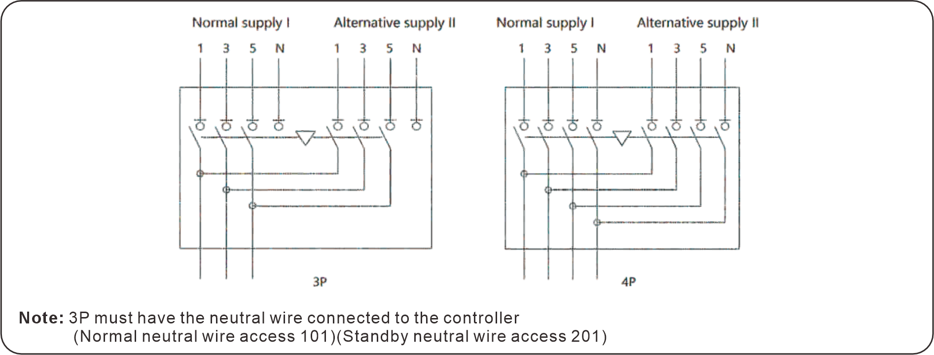
Note:(*) Maintainable
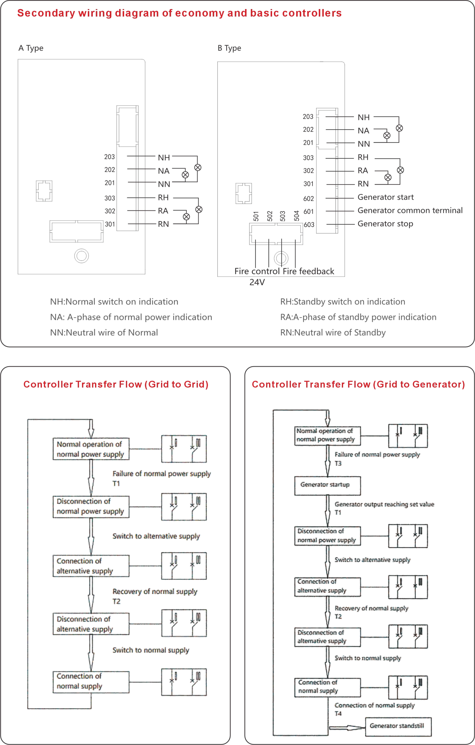
Parameters of Controller
| Type | Type A | Type B |
| Power supply and opening/closing indication | ■ | ■ |
| Automatically transfer and restore operation | ■ | ■ |
| Grid-grid | ■ | ■ |
| Grid-generator(start/stop) | – | □ |
| Three-phase monitoring commonly used to detect phase loss in power supply | ■ | ■ |
| Three-phase monitoring commonly used to detect power loss in power supply | ■ | ■ |
| Single-phase monitoring commonly used to detect phase loss in power supply | ■ | ■ |
| Single-phase monitoring commonly used to detect power loss in power supply | ■ | ■ |
| Handle manual operation | ■ | ■ |
| External wiring terminal of indicator light | ■ | ■ |
| Fire control linkage(24VDC) | – | □ |
| Fire feedback | – | □ |
| Note: “■” Standard, “□” Optional, “-” No | ||
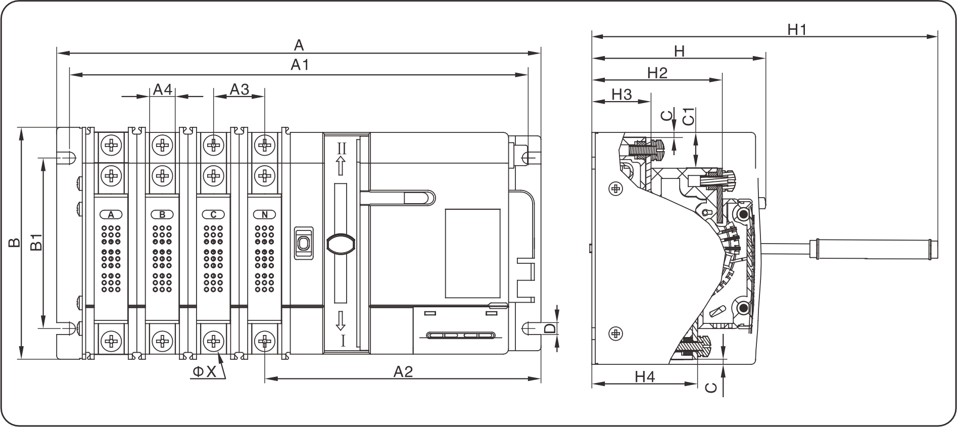
| Specifications | A | B | H | A1 | B1 | A2 | A3 | A4 | H1 | H2 | H3 | H4 | C | C1 | D | φX | ||||
| 2P | 3P | 4P | 2P | 3P | 4P | |||||||||||||||
| 63 | 171 | 193 | 215 | 138 | 68 | 144 | 166 | 188 | 106 | 136 | 22 | 13 | 152 | 52 | 24 | 43 | 2 | 13 | 5.2 | 6 |
| 125 | 229 | 259 | 289 | 136 | 102 | 214 | 244 | 274 | 100 | 162 | 30 | 15 | 240 | 77 | 35 | 62 | 4 | 21 | 7 | 6 |
| 250 | 302 | 347 | 393 | 170 | 128 | 283 | 328 | 374 | 125 | 207 | 45.5 | 25 | 257 | 96 | 44 | 79 | 4 | 22 | 9 | 8 |
| 630 | 460 | 528 | 596 | 255 | 192 | 433 | 501 | 569 | 188 | 325 | 68 | 49 | 367 | 144 | 65 | 118 | 6 | 40 | 13 | 12 |
Note:The operating handle is usually removed and used for emergency or manual operation