Skip to content
 | Type | Operating and Installation Conditions |
| Ambient temperature | -5°C ~ +40°C |
| Installation altitude | ≤2000m |
| Max humidity at 40°C | ≤ 50% |
| Max humidity at 20°C | ≤ 90% |
| CZM9 | – | 125 | M | 3P | 125A | W2 |
| Model | Shell frame | Breaking capacity | Number of poles | Rated current | Controller code | |
| Dual power automatic transfer switch | 63(16~63A) | M: Standard type | 3:3P 4:4P | 10, 16, 25, 32, 40 50, 63, 80, 100, 125 140, 160, 180, 200 225, 250, 315, 400 500, 630, 800 | Default:LED Y: LCD W2: Split LED display W3: Split LCD display | |
| 125(16~125A) | ||||||
| 250(100~250A) | ||||||
| 400(250~400A) | ||||||
| 630(400~630A) | ||||||
| 800(630~800A) |

| Type | CZM9 | |||||
| Shell frame | 63 | 125 | 250 | 400 | 630 | 800 |
| Rated working current In(A) | 10,16,20,25 32,40,50,63 | 16,20,25 32,40,50,63 80,100,125 | 100,125,140 160,180,200 225,250 | 250, 315 350, 400 | 400,500,630 | 630,800 |
| Number of poles | 3, 4 | |||||
| Electrical class | Class CB | |||||
| Use category | AC33iB | |||||
| Rated working voltage Ue(V) | AC380, 400 | |||||
| Rated insulation voltage Ui(V) | AC690 | AC800 | ||||
| Rated impulse withstand voltage Uimp(KV) | 8 | |||||
| Rated short-circuit breaking capacity Icn(KA) | 15 | 25 | 25 | 35 | 35 | 35 |
| Electrical life | 1000 | 1000 | 500 | |||
| Mechanical life | 5000 | 3000 | 2500 | |||
| Rated working system | Uninterrupt working system | |||||
| Overvoltage transfer setpoint | AC230V-AC300V | |||||
| Undervoltage transfer setpoint | AC150V~AC210V | |||||
| Contact switch time | <4s | |||||
| Disconnection delay | 1s-240s continuously adjustable | |||||
| Shutdown delay | 1s-240s continuously adjustable | |||||
| Function | Full-function type |
| Manual mode | ■ |
| Automatic mode | ■ |
| Motor protection function | ■ |
| Main contact working position (performing circuit breaker) | |
| Normal power supply closed | ■ |
| Reserve power supply closed | ■ |
| Double break | ■ |
| Automatic control | |
| Monitoring normal power supply | ■ |
| Monitoring reserve power supply | ■ |
| Self-throwing and self-reset | ■ |
| Self-throwing and non self-reset | ■ |
| Reserve for each other | ■ |
| Power grid-power grid | ■ |
| Power grid-power generation | ■ |
| Phase failure instantaneous protection | ■ |
| Under-voltage protection 150-210V | adjustable |
| Over-voltage protection 230-300V | adjustable |
| Fire control function | ■ |
| Changeover time delay 0-240s continuously adjustable | ■ |
| Returning time delay 0-240s continuously adjustable | ■ |
| Frequency display | ■ |
| Communication function | optional |
| Indication | |
| N on/R on/double break indication | ■ |
| Normal power supply indication | ■ |
| Reserve power supply indication | ■ |
| Fault tripping indication | ■ |
| Parameter setting indication | ■ |
| Voltage real time indication | ■ |
| Normal three phase voltage protection | three phase |
| Reserve three phase voltage protection | three phase |
Automatic transfer switch according power supply condition and the parameter that user set to choose if transfer from one power to the other power. It’s function depends on the controller. There are 3 types(Y, w2 and w3) of controller.
The features and functionality of controller as following.
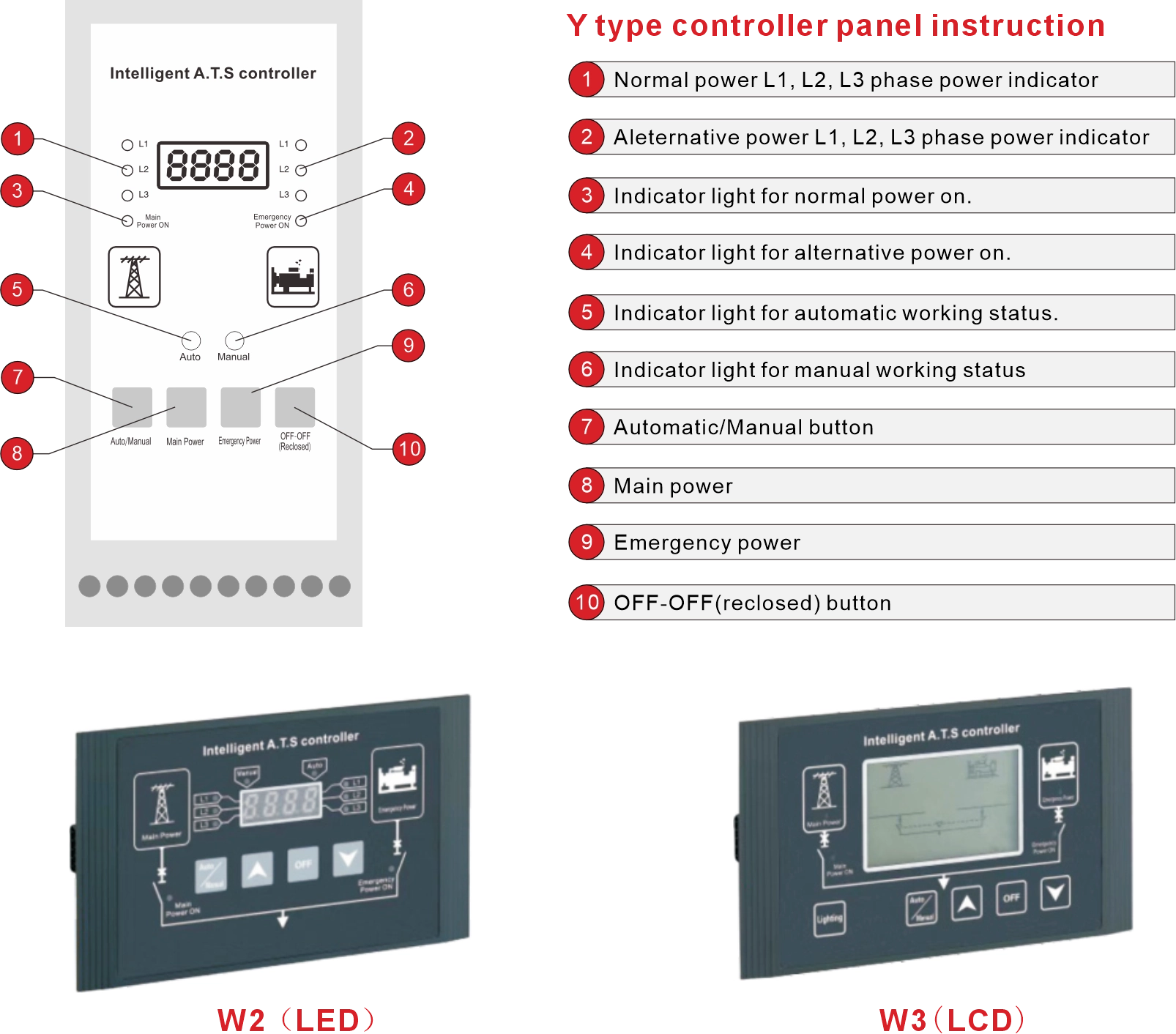
Technical data
| Controller | Y type Controller | W2 type Controller | W3 type Controller |
| Working power supply | AC160-250V 50/60Hz | DC12V(Provided by the in side of Y type controller) | |
| Installation | Integral type | Split type | |
| Position | 3 Positions | ||
| Mode of operation | Auto,manual and electro-manual operation | ||
| Voltage monitoring function | 3 phase over-voltage,under-voltage and phase loss monitoring | ||
| Frequency monitoring function | Frequency monitoring | ||
| Generator control | A set of 3A relay dry contact | ||
| Fire linkage control | Passive contact input,with a set of normally open passive signal feedback contact | ||
| Mode of conversion | According to users requirement could set at A uto Can set at Auto transfer and auto recover,Auto transfer and non-auto recovery or utility generator type mode according to user’s requirement. | ||
| Display | LED display | LCD display | |
| Conversion time delay | 0.5s-60s continuously adjustable | ||
| Return time delay | 0.5s-60s continuously adjustable | ||
| Model | Match circuit breaker | Pole | Rated short circuit making capacity(lcm) | Rated short circuit breaking capacity(Icn) | Rated current of circuit breaker (A) | Rated insulation voltage(V) |
| CZM9-63 | CM1-63 | 3 | 31.5 | 15 | 10,16,20,32 40,50,63 | 690 |
| 4 | 31.5 | 15 | ||||
| CZM9-125 | CM1-125 | 3 | 52.5 | 25 | 16,20,32,40, 50,63,80,100,125 | 690 |
| 4 | 52.5 | 25 | ||||
| CZM9-250 | CM1-250 | 3 | 52.5 | 25 | 125,160,180, 200,225,250 | 690 |
| 4 | 52.5 | 25 | ||||
| CZM9-400 | CM1-400 | 3 | 73.5 | 35 | 250,315,350,400 | 690 |
| 4 | 73.5 | 35 | ||||
| CZM9-630 | CM1-630 | 3 | 73.5 | 35 | 500,630 | 690 |
| 4 | 73.5 | 35 | ||||
| CZM9-800 | CM1-800 | 3 | 73.5 | 35 | 700,800 | 800 |
| 4 | 73.5 | 35 |
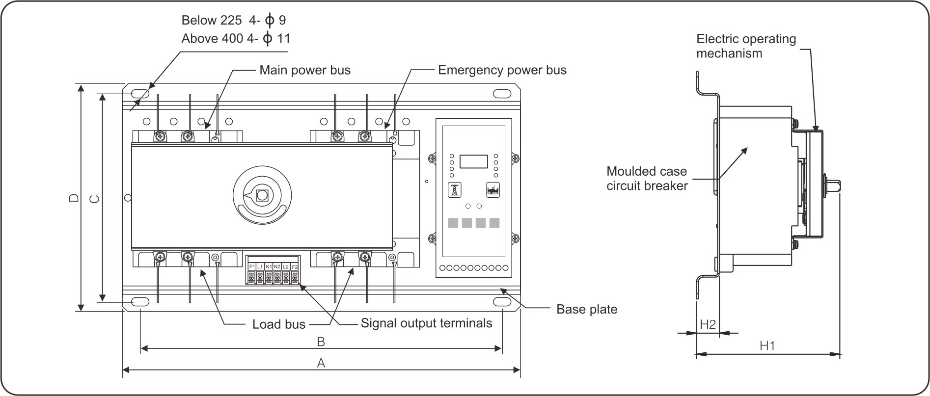
| Specification | A | D | B | C | H1 | H2 | ||
| 3P | 4P | 3P | 4P | |||||
| CZM9-63 | 380 | 405 | 250 | 340 | 365 | 230 | <160 | 25 |
| CZM9-125 | 405 | 435 | 250 | 365 | 395 | 230 | <170 | 25 |
| CZM9-250 | 450 | 480 | 250 | 410 | 440 | 230 | <190 | 25 |
| CZM9-400 | 570 | 620 | 330 | 510 | 560 | 300 | <200 | 25 |
| CZM9-630 | 680 | 740 | 330 | 620 | 680 | 300 | <250 | 25 |
| CZM9-800 | 750 | 820 | 330 | 690 | 760 | 300 | <250 | 25 |
Switch Installation
Split Type Controller Installation
Wiring must be correct and secure to ensure ATS works properly.
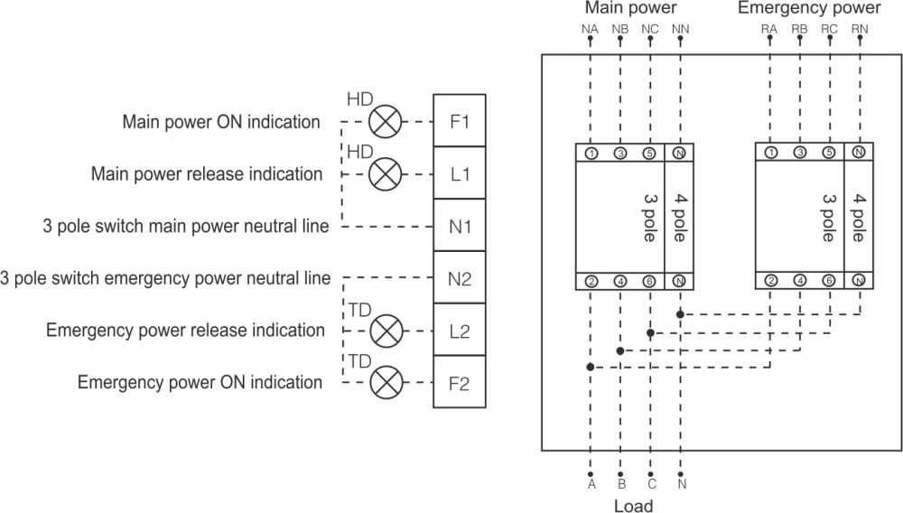 Note:This diagram applies to three-phase four-wire. When using three-phase three-wire system, the neutral line of main power connects to terminal N1 port,neutral line of emergency power connects to terminal N2 port.HD main power indication AC220V(User-provided).TD main power indication AC220V(User-provided).